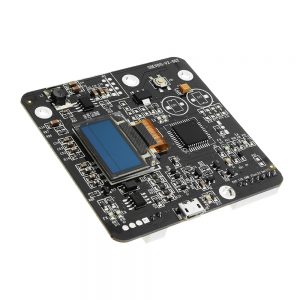
Feature:
This module uses the LM2596 chip, high efficiency (up to 92%), low heat, can be very easily used to above 3A current, in conjunction with the original TI op amp control output current, so the overall output is very stable.
This module uses the original Sanyo low ESR filter capacitor, you can make low ripple voltage to 50mV!
This module uses machine placement, reflow soldering.
This module is an adjustable buck module, the module can be adjusted from the blue adjustable resistor to change the output voltage. Input and output differential pressure is 2V, the minimum can be output 1.23V.
Module indicated IN – (negative input), IN + (positive input), OUT – (negative output), OUT + (positive output), please note must be correct connected, otherwise may cause damage to the module.
Description:
Nature of the module: Non-isolated step-down module
Rectification: Non-synchronous rectification
Input voltage: 7V – 35V
Output voltage: 1.25V – 30V
Output current: Adjustable, 3A (maximum)
Transfer efficiency: 92% (maximum)
Switching frequency: 150KHz
output ripple: 50mV (maximum) 20M Kbps
Load regulation: ±0.5%
Voltage regulation: ±2.5%
Operating temperature: -40°C to +85°C
Dimension: 48 x 23 x 14mm (L x W x H)
Battery charging method:
1. Make sure the battery float voltage and charging current, the module input voltage;
2. Adjustment constant potentiometer, the output voltage is adjusted to about 5V.
3. Use the multimeter (10A current) measuring the output short-circuit current, meanwhile adjust the constant current potentiometer make the output current reaches a predetermined charge current value;
4. Turn lamp current default is 0.1 times charging current (constant current value), if you need to adjust please adjust the turn lamp current potentiometer; (generally doesn't need adjustment)
5. Adjustment constant potentiometer allows the output voltage reaches the float voltage;
6. Connected to the battery and try to charge.
(1,2,3,4,5 steps are for the module input connected to the power supply, the output-load battery is not connected.)
LED constant current driver using method:
1. Make sure that the drive LED operating current and maximum working voltage;
2. Adjustment constant potentiometer, output voltage adjusted to about 5V.
3. Use the multimeter (10A current) measuring the output short-circuit current, meanwhile adjusting the constant current potentiometer allows the output current reaches a predetermined LEDworkingcurrent;
4. Adjustment constant potentiometer allows the output voltage reaches the maximum operating voltage LED;
5. Connect LED, test machine.
(1,2,3,4 steps are module input connect to the power supply,output-load is not connected LED lights.)
Package included:
5 x Buck module


