Arduino Kits
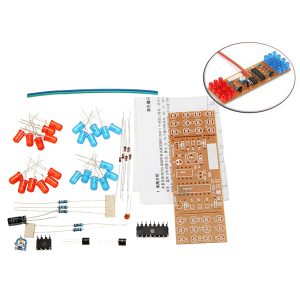
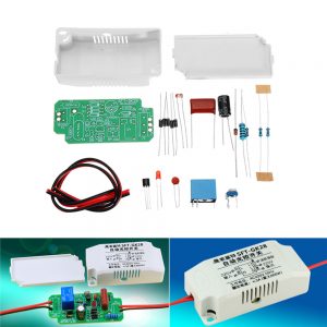
DC 3V To 6V DIY OTL Discrete Component Circuit Power Amplifier Kits Electronic Training Kits
$3.26
Parameter:
Size: 40*55*1mm(length*width*height)
Input voltage: DC 3-6V
Circuit description:
1. Q1 is the excitation amplifier, which gives the power amplifier output stage enough push signals.
2. R1 and RP2 are the bias of Q1.
3. On the R3, D1, and RP3 series-pole circuits, bias the Q3 to make it statically in a micro-conducting state to eliminate crossover distortion.
4. C3 is an anti-vibration capacitor for eliminating circuit surges.
5. Q2 and Q3 are complementary symmetric push-pull power amplifiers, which form a power amplifier output stage.
6. C2, R4 composition bootstrap circuit, R4 is current limiting resistor.
Circuit debugging:
Connect DC 3-6V power supply and adjust RP2 so that the midpoint voltage of Q2 and Q3 is 1/2 supply voltage.
Adjust RP3 so that the quiescent current of the amplifier output stage is 5-8 RP2 and RP3 so that both parameters reach the above values!
Welding step:
1. Weld resistance and zener diode first. Keep the board as close as possible.
2. Then weld the capacitance of the triode capacitor. Welded capacitors and triodes are used to pay attention to polarity.
3. The third step welding two adjustable resistors, a volume potentiometer.
4. Finally weld the three terminal blocks.
Package included:
1 X DIY OTL discrete component circuit power amplifier kits


